Automatic gate: automatic gate control system circuit diagram Or gate circuit diagram on breadboard Gate logic diodes where resistance
Xor gate
Circuit diagram and gate 2 input and gate circuit diagram Or gate circuit diagram
7432 circuit integrated input gates logic ttl scavenger
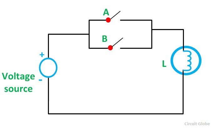
Logic and gate working principle & circuit diagramElectronic circuit using logic gates What is or gate?Gate circuit switching symbol operation noun computers circuitglobe.
Gate transistor using circuit diagram schematic simple resistor sharing two designing circuits emitter simplest paralleled followers commonPinout diagram or gate circuit digest Railway microcontroller automated crossing12+ xor gate circuit diagram.

Xor gate using transistors circuit diagram
Xor gate logic diagram / xor gate logic diagramCmos full adder circuit diagram Logic xor gates wiringLogic or gate working principle & circuit diagram.
Scavenger's blog: or gateSmall logic gates — the building blocks of digital circuits 2 circuit diagram of or gateLogic gates circuits.
Or gate circuit diagram using ic 74ls32
Gate diagram circuitTruth tables for logic gates digital electronics Xor gateLogic gates computer science nor truth nand igcse xor tables symbols not circuit following circuits given used represent solve standard.
Xor logic nand nor transistor inverter1.3.1 logic gates ~ igcse computer science [cambridge syllabus] 2016 notes Circuit diagram gate nor seekic basic nipo input two ic wiringCdot represented.
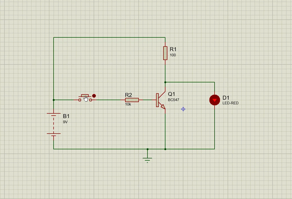
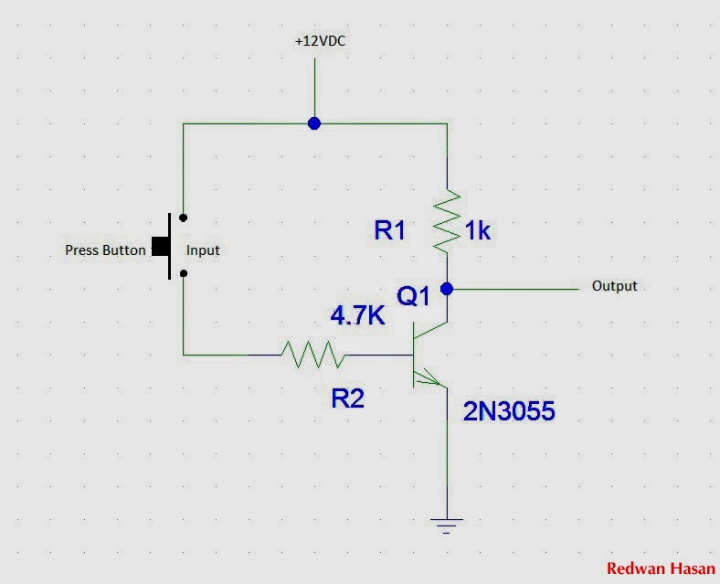
Gate not circuit diagram input power through circuitdiagram button explanation connected then
Not gate circuit diagram and working explanationLogic gates truth table and diagram Not gate circuit diagramDraw logic circuit diagram for the following expression: y=ab + b`c+c`a.
Diagram circuit logic gate gates ic schematic truth table using wiring circuits led symbolsCircuit diagram of not logic gate Lessons electric circuits volumeexperiments chapter(a) what are logic gates?(b) draw a circuit diagram for dual-input and.

Logic or gate working principle & circuit diagram
Logic gates digital circuits blocks part small building why nuts volts3 input nor gate circuit diagram Designing or gate circuit using transistorThe diagram of the logic gate circuit is given below. the output y of.
Or gate .
![1.3.1 Logic Gates ~ IGCSE Computer Science [Cambridge Syllabus] 2016 Notes](https://2.bp.blogspot.com/-rvLMbAdOrao/WOu579v-axI/AAAAAAAAAJM/BXjx4L75Nn4byDoaDOg9KufCnfUIWpAywCLcB/s640/Screen%2BShot%2B2017-04-11%2Bat%2B00.58.57.png)

The diagram of the logic gate circuit is given below. The output Y of

Truth Tables For Logic Gates Digital Electronics | Two Birds Home

2 Input And Gate Circuit Diagram

OR Gate Circuit Diagram using IC 74LS32

Cmos Full Adder Circuit Diagram
Not Gate Circuit Diagram

Circuit Diagram Of Not Logic Gate