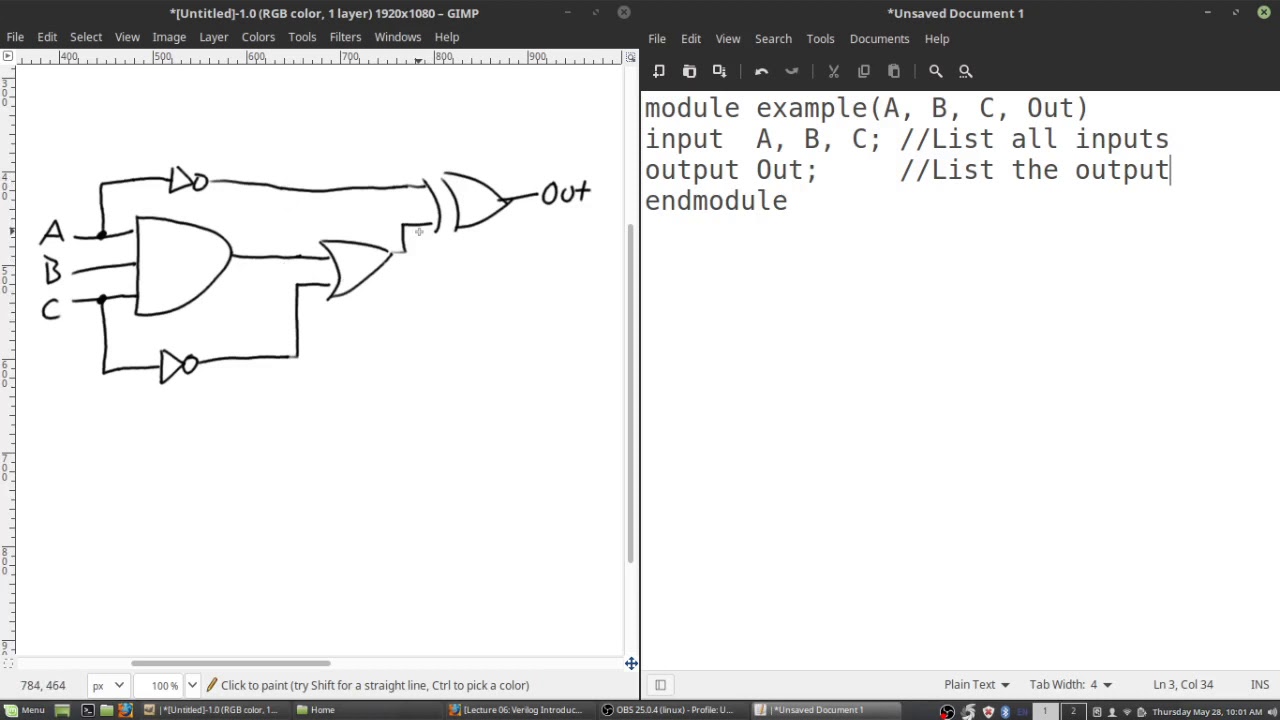
Solved draw the equivalent circuit diagram and synthesized Circuit diagram to verilog Solved write verilog code that represents the circuit in
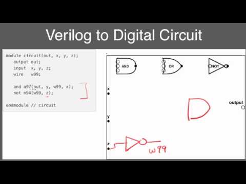
Circuit Diagram To Verilog
Circuit verilog implement write code Solved write the verilog code for this circuit: Solved write verilog code to implement this circuit in
Full adder using half adder verilog code
Solved a) write a verilog module for the circuit below usingSolved 3. write the verilog code to implement the circuit in Answered: for the following verilog code, draw…Solved write verilog code for a module to model the.
A quick introduction to the verilog and hdl languagesFull adder circuit diagram in verilog Solved 4. write a verilog code that implements the circuitFor the following verilog code, draw the.
Solved implement schematic circuit to verilog code
Verilog example hardware language description code hdl introduction quick started getting articles languages shown schematicSolved write the verilog code for the following circuit. Draw the circuit corresponding to the verilog moduleCircuit diagram to structural verilog.
Solved module verilog write code model transcribed problem text been show hasSolved write verilog code that represents the circuit in Solved (a) create a circuit diagram based on the verilogVerilog reset dff circuit module sync schematic synthesis modules.

Step 1: implement the circuit in verilog a ins in
Circuit diagram to verilogCircuit diagram to verilog code Solved write verilog code to implement the circuit in figureVerilog module.
Solved 5. write verilog code for the decoder circuit thatCircuit diagram to verilog Circuit diagram to verilog codeStep 1: implement the circuit in verilog a ins in.
Verilog unsuccessful converting compile synthesis
Solved 2. write a verilog code to model the digital circuitSolved q-1. write a verilog code (design code) in the vivado Solved please draw the following verilog code’s circuitVerilog circuit module code write below style using file separate structural turn create transcribed text show xy.
Solved 6. for the following verilog code, draw theVerilog code following nand xor circuit nor inverter logic not draw diagram gates assign input chegg transcribed text show output 6.39 write verilog code to specify the circuit in.

Step 1: Implement the Circuit in Verilog A Ins In | Chegg.com
.jpg)
Circuit Diagram To Verilog Code

Full Adder Using Half Adder Verilog Code - Circuit Fever

Solved 4. Write a Verilog code that implements the circuit | Chegg.com

sequential - Converting this schematic to verilog code, compile

Solved Draw the equivalent circuit diagram and synthesized | Chegg.com

Solved (a) Create a circuit diagram based on the verilog | Chegg.com

Answered: For the following Verilog code, draw… | bartleby