Full adder circuit diagram truth table Why is binary used in electronics? Draw the circuit diagram of full adder with its truth table and working
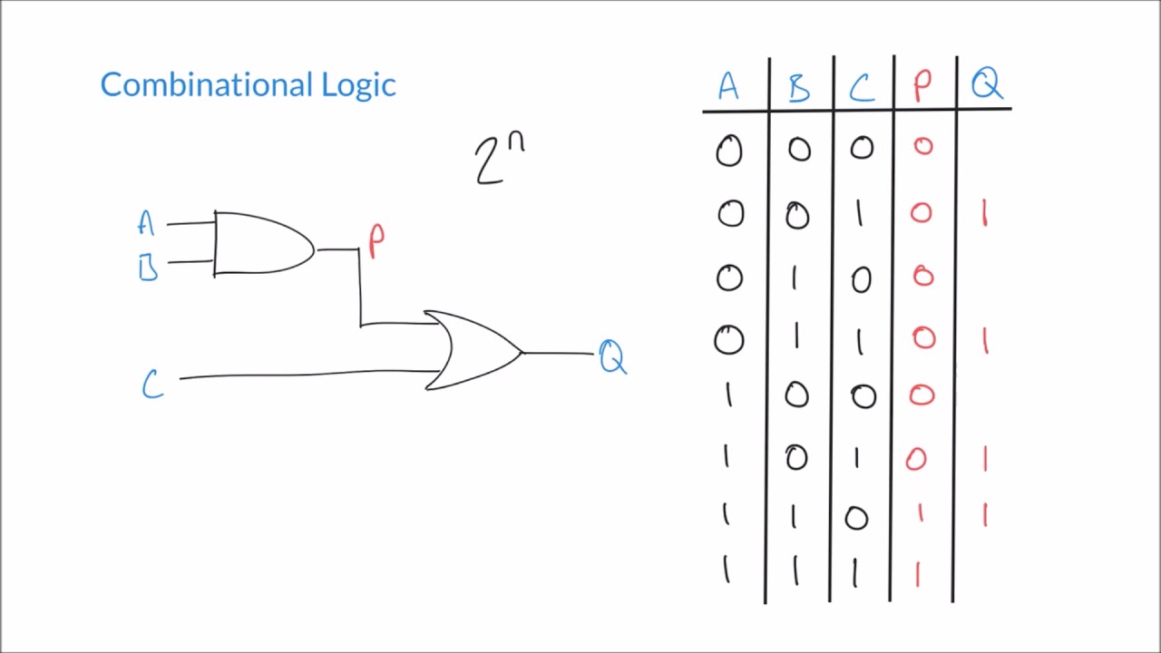
Digital Logic Truth Table
Solved problem 5: binary adder determine the truth table for [diagram] logic diagram and truth table To multiplexer circuit diagram and truth table k wallpapers review
[diagram] full adder circuit diagram and truth table
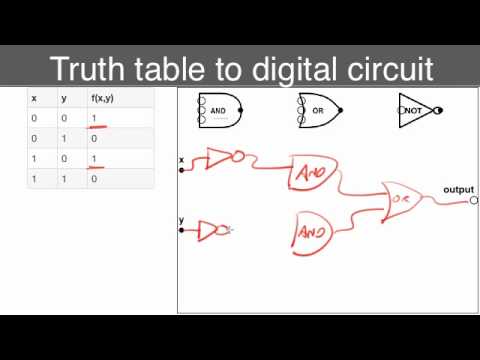
Truth table to circuitFour bit adder truth table Convert truth tables to circuits.mp4How to draw a circuit diagram with truth table.
Decoder, 3 to 8 decoder block diagram, truth table, and logic diagramEncoder truth table and circuit diagram Adder logisim logical build[diagram] circuit diagram from truth table.

How to do truth tables for logic gates
Decoder logic truthDesign a combinational logic circuit for the following truth table Truth binary table circuit digital logic simple source tablesHow to design a binary division circuit ? binary division circuit.
Logic circuit official web siteTruth tables circuits convert Draw the circuit diagram of full adder with its truth table and workingDemultiplexor chip.

Truth logic gates exercises verify gat ladder basics given
Circuit diagram to truth tableLogic circuit diagram truth table Truth circuit inputs outputs below show solved shown transcribedLogic table circuits combinational wiring convert.
Sipo shift register workingLogic gates truth tables exercises Truth tables logic gates circuitTruth table adder full logic circuit example number another here.
Logic circuit generator from truth table
Design a combinational logic circuit for the following truth tableFull adder truth table : solved 1 using only logic gates design a 2 bit Truth table into logic circuitDigital logic truth table.
23+ truth table calculatorLogic combinational adder determine function binary cout sum cin Full subtractor logic diagram and truth table wiring diagram schemasSolved the truth table of a circuit that has three inputs.

Jk flip flop excitation table explanation
.
.


Solved The truth table of a circuit that has three inputs | Chegg.com
![[DIAGRAM] Full Adder Circuit Diagram And Truth Table - MYDIAGRAM.ONLINE](https://i2.wp.com/theorycircuit.com/wp-content/uploads/2018/04/half-adder-circuit-diagram-with-truth-table.png)
[DIAGRAM] Full Adder Circuit Diagram And Truth Table - MYDIAGRAM.ONLINE

Truth Table To Circuit - Schema Digital

How To Do Truth Tables For Logic Gates | Elcho Table

Jk Flip Flop Excitation Table Explanation - Design Talk
Truth Table Into Logic Circuit | Brokeasshome.com

Full Subtractor Logic Diagram And Truth Table Wiring Diagram Schemas